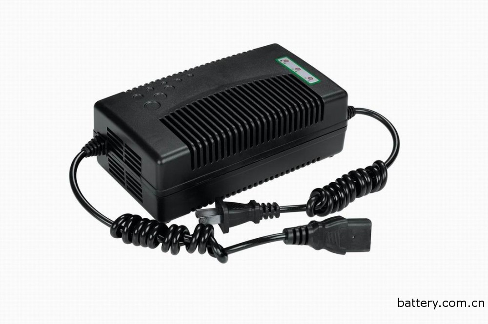
First, electric car charger introduction:
An electric car charger is a charging device specially designed for the battery of an electric bicycle! Classification of chargers: Differentiated by using and without power frequency transformers, they can be divided into two categories. Commonly used switching power supply chargers are divided into two types: half-bridge type and single-excitation type. The single-excitation type is divided into two types: forward type and flyback type.
Second, how to choose electric car charger:
For the problem of electric vehicle charging, the most common problems that make electric vehicle users feel headaches are: "The cruising range is obviously shortened" "Easy to explode when charging" "The charger failure rate is high".
Gaobiao Technology recommends that consumers choose products with high brand reputation, good reputation and high market share when purchasing electric vehicle chargers. Many inferior chargers on the market are prone to overcharging and undercharging. The phenomenon of water loss and vulcanization is a great hidden danger to the personal and property safety of consumers. These products are lacking in functional design. The reason for choosing the big-name charger products is that these high-quality products are designed with many charging protection functions, such as positive and negative pulse charging technology, intelligent timing protection function, and temperature. Automatic compensation function, grid instantaneous shock protection, super moisture and corrosion resistance, pressure limiting charging to prevent water loss, overcurrent protection battery polarization, overload protection to prevent failure, rectangular pulse extension life, cross current charging life longer, etc. Increased safety and efficiency of charging.
Consumers still can't relax their vigilance after purchasing the charger of the big brand. In daily life, they should always check the electric vehicle charger, and also pay attention to check the electric vehicle battery . In many cases, the aging problem of the battery will also give people The car brings safety problems. Grasp the charging time of the electric vehicle battery during use and develop a good charging habit.
Third, the working principle of electric car charger:
220v AC power is suppressed by T0 bidirectional filtering, D1 rectification is pulsating DC, and then C11 filtering forms a stable DC current of about 300V. U1 is a TL3842 pulse width modulation integrated circuit. Its 5 feet are the negative pole of the power supply, 7 feet are the positive pole of the power supply, 6 feet are the pulse output and directly drive the FET Q1 (K1358). The 3 pin is the maximum current limit. Adjusting the resistance of R25 (2.5 ohms) can adjust the maximum current of the charger. .
Pin 2 is voltage feedback and can adjust the output voltage of the charger. The 4-pin external oscillating resistor R1 and the oscillating capacitor C1. T1 is a high frequency pulse transformer with three functions:
The first is to step down the high voltage pulse to a low voltage pulse. The second is to isolate the high voltage to prevent electric shock.
The third is to provide working power for uc3842. D4 is a high-frequency rectifier tube (16A60V) C10 is a low-voltage filter capacitor, D5 is a 12V Zener diode, U3 (TL431) is a precision reference voltage source, with U2 (optocoupler 4N35) to automatically adjust the charger voltage. Adjust w2 (fine tuning resistor) to fine tune the charger voltage. D10 is the power indicator. D6 is the charging indicator.
R27 is the current sampling resistor (0.1 ohm, 5w). Change the resistance of W1 to adjust the inflection point current of the charger to float.
(200-300 mA) When the power is turned on, there is a voltage of about 300V on the C11. This voltage is loaded all the way to Q1 via T1.
The second pass through R5, C8, C3, reaches the 7th foot of U1. Force U1 to start. U1's 6-pin output square wave pulse, Q1 works, and current flows through R25 to ground. At the same time, the T1 secondary coil generates an induced voltage, and through D3, R12 provides reliable power to U1. The voltage of the T1 output coil is rectified and filtered by D4 and C10 to obtain a stable voltage. This voltage charges the battery all the way through D7 (D7 prevents the battery from flowing back to the charger).
The second path is R14, D5, C9, which is LM358 (dual operational amplifier, 1 pin is power ground, 8 pin is power positive) and its peripheral circuit provides 12V working power. D9 provides the reference voltage for the LM358, and the second and fifth legs of the LM358 are divided by R26 and R4. During normal charging, the upper end of R27 has a voltage of about 0.15-0.18V. This voltage is applied to the third leg of LM358 via R17, and a high voltage is sent from pin 1. This voltage passes through R18 all the way, forcing Q2 to turn on.
D6 (red light) lights up, the second way is injected into pin 6 of LM358, 7 pin outputs low voltage, forcing Q3 to turn off, D10 (green light) is off, the charger enters the constant current charging phase. When the battery voltage rises to about 44.2V, the charger enters the constant voltage charging phase, and the output voltage is maintained at about 44.2V. The charger enters the constant voltage charging phase, and the current gradually decreases. When the charging current is reduced to 200mA-300mA, the voltage at the upper end of R27 drops. The voltage of pin 3 of LM358 is lower than 2 pin, the output of pin 1 is low voltage, Q2 is turned off, and D6 is extinguished. At the same time, the 7-pin output high voltage, this voltage makes Q3 turn on all the way, D10 lights up. The other way through D8, W1 reaches the feedback circuit, causing the voltage to drop. The charger enters the trickle charging phase. Charging ends after 1-2 hours.
Fourth, electric vehicle charger common faults:
1: The power supply does not start: plug in the power supply, the large capacitor has 300V voltage, unplug the power supply and measure the large capacitor 2 terminal or 300V voltage without falling. After discharging the capacitor, replace the startup resistor. The starting resistor is in the power input section, with a resistance of 150K and a power of 2W.
2: The power supply does not start: plug in, the large capacitor has 300V voltage at the 2nd end, unplug the power supply, the voltage of the large capacitor drops slowly, and all the boards are checked for de-soldering. After the repair is completed, replace 3842 with new ones. , power on the test machine,
3: Flashing light: first repair the board and test it again. If it is still flashing, please check the sampling resistance at the output. 0.1 ohms. 3W power. Connect to the negative side of the output line and replace it with a new one.
4: The output voltage is high, the power is on, the voltage is higher than 70V, the charging does not turn the lamp, the circuit board is repaired once again, and the machine is tested again. If the voltage is still high, please replace the optocoupler, test again, or output high. Replace the 431 reference regulator and test the machine again.
5: Howling, fever, insufficient charging: Power measurement of large capacitor voltage, as long as it is lower than 300V, the general capacitor fails, can be replaced.
6: Severe fever, please replace the fan.
7: The output voltage is unstable. First, the circuit board is repaired once. After the test machine, the output capacitor 63V470UF capacitor can be replaced with a new test machine.
8: Charging does not turn the light, test the data with the detector, and then replace the 358 or 324 with the new test machine. 9: The charging is unstable, sometimes it can be charged, sometimes it can not be washed, use the tester to test the data, then the input and output power lines, all replaced, repair welding circuit board test machine.
10: Power-on fire insurance: first check the power tube breakdown, if not, replace all four rectifier diodes, test machine.
11: no output, no power, test the machine, the large capacitor 2 end has 300V voltage, and slowly decline, first check the output terminal large diode breakdown does not, repair welding, test again.
12: Power on 2 red lights: Power on test machine, no-load voltage is normal, then replace 358 or 324 with new test machine.
13: No output when power is on, it can start normally, the indicator light is normal, first replace the output line, and short-circuit the relay test machine for the charger with relay.
14: Power flashing light, please repair the transformer pins, and then test the machine. If it is still, please check whether the 431, photocoupler, and output diodes are short-circuited, the transformer core is loose, and the power input part is 10 ohms. Open the road, or replace the 3842 test machine again.
15: Charging does not turn the light, first test the data with the tester, generally the new battery voltage is not higher than 59.5, the battery is not higher than 58.8 for about half a year, it is normal, higher than this voltage may not turn the light.
16: Low output voltage: repair welding circuit board. Test the machine, then replace the input and output capacitors with the new test machine 17: the output is low, hot, if the output voltage is lower than 40 V, and the power tube, the transformer is hot, generally the transformer has problems,
18: Difficult to start, sometimes can not start, sometimes repair the circuit board, after the test machine, if you still need to replace the input part of the small capacitor again test machine.
19: After burning 3842, 3842, the test machine plugged in and heard a sound of a click. This is to measure the voltage of the large capacitor 2 terminal 300V slowly, indicating that the 3842 is broken down again, first repair the circuit board, check the transformer lead Whether the foot is loose or the lead is disconnected, the output part of the large diode is open circuit, and the circuit board is broken.
20: The above faults are suitable for common faults of most single-tube circuit chargers on the market. You can consult technical personnel at any time during the operation.
DroneLiPo Battery Blance Charger,Li-Ion Battery Charger,12S Battery Charger,Li Fe Battery Charger,Charging HUB
Drone LiPo Battery Blance Charger,Li-Ion Battery Charger,12S Battery Charger,Li Fe Battery Charger,Charging HUB
shenzhen GC Electronics Co.,Ltd. , https://www.jmrdrone.com