Application of Vortex Flowmeter in the Measurement of Compressed Air in Taiyuan City Vocational and Technical College Fan Bohong, Xue Hongmin, China Aluminum Shanxi Branch, Hejin 04330, Shanxi, China This paper describes the working principle and characteristics of vortex flowmeter, and introduces the use of type 2 The vortex flow sensor and the 5D 2, 2 intelligent flow totalizer are used to measure the high-pressure wind measurement system, and combined with the experience to put forward reasonable suggestions on the precautions during installation and operation.
Reading key words vortex flowmeter; compressed air; measurement classification number; document identification code article compilation è€16730046 plus vortex flowmeter working principle and characteristics vortex flowmeter is based on the principle of Kamen vortex street to measure the international advanced level The flowmeter, because it has the advantages that other flowmeters can not have, has been rapidly developed since the 1970s. According to relevant information, the proportion of vortex flowmeters in developed countries such as Japan and Europe has risen sharply. Widely used in various fields, it will dominate the flow meter in the future and is the ideal replacement for orifice flowmeters.
The vortex flowmeter is provided with a vertical column in the measuring pipe, and the fluid alternately generates a regular vortex through both sides of the column, and this vortex is also called a Karman vortex street. The release frequency of the Karman vortex street is related to the flow velocity of the fluid and the width of the column. It can be called the Stroha number æ± flow rate by the following formula; 1 The width of the column can be calculated by the formula, and the width of the column and the width of the column 1 Under constant conditions, the frequency of the Karman vortex street is proportional to the flow rate of the fluid. Therefore, by measuring the release frequency of the Karman vortex street, the instantaneous flow rate of the fluid in the pipe can be calculated. The vortex release frequency of the series vortex flow sensor is detected by the piezoelectric element inside it based on the stress that the vortex alternately acts on the detecting sensor.
The measurement system consists of a high-pressure wind flow measurement system consisting of a Shanghai Kent 2 vortex flow sensor and a 12 intelligent flow totalizer. The vortex sensor is mainly purchased by a corner post probe in the sensor with a magnifying plate connecting rod vortex generator assembly, which can be used for the measurement of superheated steam saturated vapor compressed air and general gas. In this measurement system, the vortex flow sensor is mounted on a vertical pipe, which sends a pulse signal corresponding to the high pressure wind flow to the intelligent flow totalizer.
12 intelligent flow totalizer adopts advanced single-chip technology, which can be used for flow measurement with street elimination sensor or orifice flow sensor. It has full Chinese LCD display screen, which can display the accumulated heat vortex frequency of heat accumulated flow without instantaneous flow. A variety of information such as medium pressure temperature density time and date, as well as a wealth of functions such as small flow automatic compensation for stop current compensation and automatic copying. The temperature and pressure signals can also be automatically compensated for temperature pressure. It will come from the flow sensor and output a 4,20 signal proportional to the instantaneous flow to facilitate the same connection.
Precautions in use Proper installation of the sensor is the primary prerequisite for ensuring accurate and reliable measurement. If the error in the installation location and mode selection affects the measurement accuracy, it will affect the service life of the sensor and even damage the sensor.
To ensure the proper installation of the sensor in the straight pipe section, the length of the upstream straight pipe section is required to be 1540. Where the length of the downstream section is 5, it can be adjusted according to the condition of the upstream and downstream pipelines to ensure the measurement accuracy. The sensor should also avoid installing the sensor on the very long overhead pipe. After a long time, the sensor sag is easy to leak the seal between the sensor and the flange. If it is necessary to install, it must be at the upstream and downstream of the sensor. Set fastening devices such as pipe brackets.
The sensor should be installed on the pipe with strong vibration. If it has to be installed, vibration damping measures must be taken. Pipe fastening devices are installed at the upstream and downstream of the sensor, and the vibration is stronger at the exit of the air compressor. The sensor cannot be installed and should be installed behind the gas tank.
According to the measuring fluid, choose the appropriate installation method. When measuring the high pressure wind, you can choose to install the sensor on the horizontal pipe or vertical pipe. However, if the water content in the high pressure wind is high, the sensor should be installed in the pipeline when the horizontal installation is high. At the point of vertical installation, the gas flow direction should be from bottom to top. Regardless of the horizontal or vertical installation, the fluid flow must be maintained with the flow arrow on the sensor body. The external environment requires that the sensor be installed in a place where the temperature changes greatly and the thermal radiation range of the device. If it must be installed, it should be insulated. Ventilation measures. When installing in a humid environment containing corrosive gases, moisture and isolation measures must be taken. In addition, because electrical noise can interfere with the correct measurement of the sensor, the installation location should be away from interference devices such as high-power transformer motors.
艮12 intelligent flow totalizer has a good Chinese interface for user convenience. Correct parameter setting is to ensure that the measurement accuracy measurement does not require pressure temperature compensation. Therefore, the measurement signal is set to the volume flow rate under the working state, the input signal selection frequency, and the unit of the instantaneous flow rate is also default, and no user setting is required.
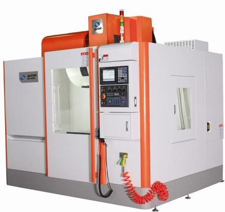
In general, computer numerical control milling machine (CNC) machining is a deductive manufacturing technique that programs 3-axis linkage, complex to 5-axis linkage, drives milling cutters to remove layers from solid blocks called blanks to produce finished parts. CNC milling is one of the main types of CNC Machining, which uses cutting tools that rotate at a speed of several thousand to tens of thousands of revolutions per minute (RPM) to precisely remove materials to obtain parts with complex surfaces. In addition to milling, CNC machining is also equipped with drills, boring tools, thread cutters and other tools to complete different part features at once. CNC machining produces parts based on a computer-aided design (CAD) model that is sent to a CNC machine through computer-aided manufacturing (CAM) software.
CNC Machining centers developed from CNC milling machines. The biggest difference compare to CNC milling machines is that the machining center has the ability to automatically exchange machining tools, by installing tools for different purposes on the tool magazine, the machining tools on the spindle can be changed through the automatic tool changing device in a single clamping device to achieve a variety of machining functions.
|
CNC Milling Finish |
|
|
Process |
Roughness Ra(um) |
|
Cylindrical milling cutter milling (rough) |
12.5~3.2 |
|
Cylindrical milling cutter (fine) |
3.2~0.8 |
|
Cylindrical milling cutter (precision) |
0.8~0.4 |
|
Cylindrical milling cutter (rough) |
12.5~3.2 |
|
Cylindrical milling cutter milling (fine) |
3.2~0.8 |
|
Cylindrical milling cutter milling (precision) |
0.8~0.4 |
|
Cutter milling (fine) |
12.5~3.2 |
|
End milling cutter (rough) |
3.2~0.4 |
|
End milling cutter (precision) |
0.8~0.2 |
|
High speed milling (rough) |
1.6~0.8 |
|
High speed milling (fine) |
0.4~0.2 |
CNC milling accuracy
CNC milling centers and high-Precision Machining centers. Ordinary machining center, resolution of 1μm, maximum feed speed of 15 ~ 25m / min, positioning accuracy of about 0μm. High-precision machining center, resolution of 0.1μm, maximum feed speed of 15 ~ 100m / min, positioning accuracy of about 2μm. Between 2 and 10 μm, with a ± 5 μm more, can be called precision grade. FCE equipped with different grade and different size CNC milling center. Take in to account into both economic and quality in parallel.
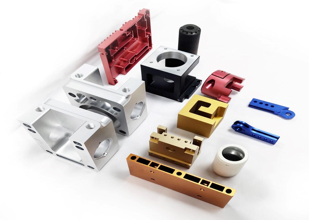
CNC Finishing surface treatment
Post-processing is the final step in the CNC machining process. In a quick guide, we offer a lot of surface treatments to complete your final parts and get them to meet strict specific requirements. It should be noted that in CNC machining, post-processing is in optional, as the quality of the machined parts is already very high.
Anodized
The anodizing process allows the part to obtain excellent corrosion resistance, increasing the hardness and wear resistance of the surface. Anodizing is also the most common pre-painting treatment, which can help the painted surface to obtain good adhesion. We typically apply two types of anodizing in our production: Type II, corrosion resistant; Type III is thicker, adding a layer of wear resistance. Both anodizing processes can achieve a variety of color effects.
Polishing
Grinding polish, it offers the fastest turnaround parts and does not require post-processing. The surface finish of the grinding part is equivalent to 125 um in Ra, and the requirements can be increased to 63, 32 or 16 um Ra. Minor tool marks may still be visible on the last part.
Powder coatings
Powder Coating is thermoplastic powder spraying directly on the processed part. The sprayed parts are then baked in an oven to form a durable, abrasion- and corrosion-resistant plastic coating. In the powder coating process, its color, brightness, surface roughness can be customized.
Shot blasting
Shot peening is the high-speed spraying of beads of different hardnesses and sizes onto the surface of the part. To get different textures and brightness of the surface. Since the surface has been hit by similar forging beads, the hardness and wear resistance of the surface have also been enhanced.
Design of CNC machining
CNC machining is a universal machining process, especially parts that can be cut and machined can be achieved through CNC, from simple shape shapes to complex curved structures. However, as with every manufacturing technique, CNC machining has some design limitations. We break them down as follows to ensure that your products are optimally designed to better fit the CNC machining process.
General Tolerance
When designing parts, the size of each part is different according to the application environment, working conditions, etc., and the requirements for the machining accuracy of the workpiece are also different. Although CNC machining can achieve very high machining accuracy, we should also be aware that demanding machining accuracy and accuracy (strict product tolerances) usually mean Longer production times and higher costs. If a specific tolerance is not specified in the product design, we recommend choosing at the following levels.
|
Permissible deviations in mm for ranges in nominal lengths |
Tolerance Class Designation(Description) |
|||
|
fine |
medium |
coarse |
very coarse |
|
|
0.5 up to 3 |
±0.05 |
±0.1 |
±0.2 |
-- |
|
over 3 up to 6 |
±0.05 |
±0.1 |
±0.3 |
±0.5 |
|
over 6 up to 30 |
±0.1 |
±0.2 |
±0.5 |
±1.0 |
|
over30up to 120 |
±0.15 |
±0.3 |
±0.8 |
±1.5 |
|
over120upto400 |
±0.2 |
±0.5 |
±1.2 |
±2.5 |
|
over 400up to 1000 |
±0.3 |
±0.8 |
±2.0 |
±4.0 |
|
over 1000up to 2000 |
±0.5 |
±1.2 |
±3.0 |
±6.0 |
|
over 2000 up to 4000 |
-- |
±2.0 |
±4.0 |
±8.0 |
The highest precision of our equipment is 0.001, and the recommended most precise machining requirements do not exceed +/-0.005mm
Interior angle
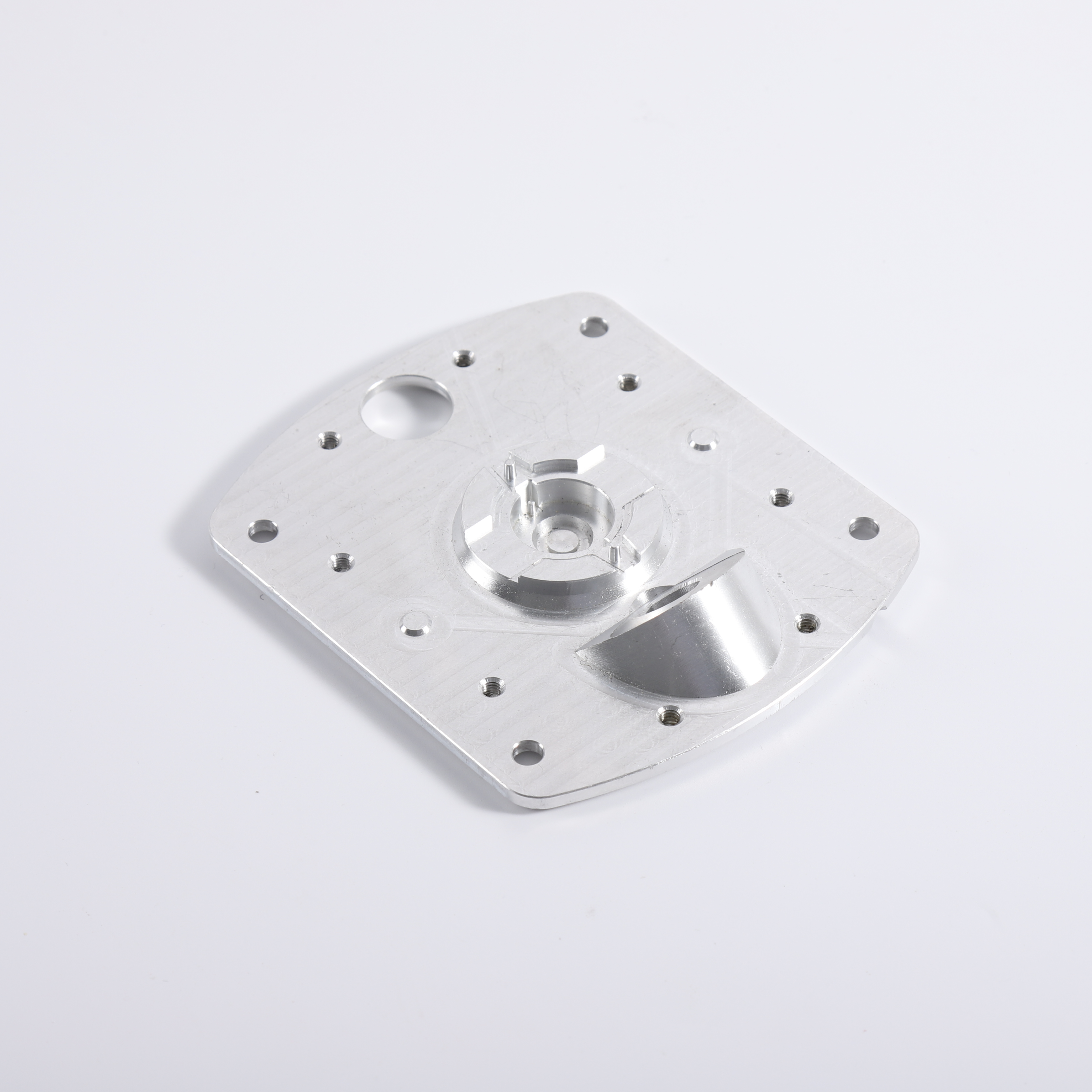
All internal vertical edges of our products need to have rounded corners instead of right angles. This is because the tools used in CNC milling are cylindrical, which means they cannot produce inner right-angled edges. The fillet required by this process is called the inner corner fillet. When designing parts, the larger the inner corner fillet, the more efficient the production process. Because of the larger fillets, larger diameter milling cutters can be used to increase milling speed, and fewer swaps can be made to improve accuracy.
Undercut
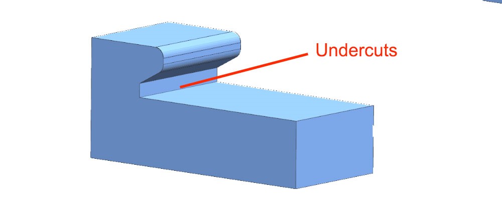
Undercut cannot be machined with standard milling cutters, so the use of retract slots for parts should be avoided when designing CNC machined parts. In particular, for non-standard inner contour shapes, customized machining tools are required, which will greatly increase processing time and costs. Secondly, if undercut can not be avoided, due to the limited length of cnc tools, the undercut can not be too deep. If they are too deep or the location is difficult to reach, they will not be able to be produced because the CNC tool cannot reach the machining location.
Chamber wall thickness
CNC machining requires your part design to meet minimum wall thickness requirements. In general, it is recommended to choose the thickest possible and avoid very thin or characteristic walls. This is because CNC tools processing thin-walled parts will cause vibration deformation, which may cause interruptions or damage, and the size is out of specification. The standard minimum wall thickness for CNC machined metals is 0.030" (0.76 mm) and for plastics is 0.060" (1.5 mm).
Thread
When designing parts, it is useful to choose the largest possible thread size because smaller taps have a higher risk of breaking during production. If possible, avoid using deep hole threads as they lead to higher production costs, especially when custom tools are required.
Metal
In principle, materials with high hardness are easier to process because better processing accuracy can be obtained, but they are limited by the hardness of processing tools, so the hardness of the generally recommended parts is 8 ~ 60HRC, and for metal materials, the hardness is greater than stainless steel Followed by cast iron, followed by copper, and finally aluminum, while the processing of ceramics, plastics, etc. belongs to the processing of non-metallic materials. Fast production time.
Polymer
Although CNC can process thermoplastics, the material properties of polymers still have many difficulties for CNC processing. First, due to poor thermal conductivity, many thermoplastics melt or bend when in contact with CNC milling machines or drill bits. Secondly, the processing of plastics, because the hardness is low, the size accuracy caused by the knife during product clamping and processing is not high. For those parts that do not have special requirements for the strength and hardness of the metal, thermoplastics can provide a cheaper alternative.
Cost optimization of machined products
Simplify product design
Simplifying product design while taking into account functionality usually saves production time and reduces production costs. Because the manufacture of complex structures and surfaces often requires complex longer passes, more layering to obtain the same fine contour quality. This means higher production costs.
Reduce cutter changes
Using the same milling machine machining features, larger and same internal fillets, can reduce the number of tools used to reduce machining time. For example, if a workpiece needs a 10mm end face milling cutter to process some features, it also needs a spherical milling cutter to process a curved surface, and a 2mm milling cutter to process a fine groove, which will require repeated tool changes and reduce the machining efficiency
Proper material selection
The choice of raw material for machining can have a significant impact on production time and costs for CNC machining. If possible, choose a material with good processability, such as brass or aluminum. For those applications that do not require metal hardness and strength, CNC machining of engineering plastics like PMMA and ABS also helps to reduce costs because the material blank is cheaper, and the processing efficiency is higher.
Tolerance and wall thickness
Higher tolerances and thinner wall thicknesses also increase THE CORRESPONDING CNC machining costs, as it takes time to achieve higher precision cutting. If your product or component can accept a larger size range, choose a lower tolerance to reduce production time and costs. The same is true for wall thickness: a larger wall thickness margin should be chosen.
Choice of surface treatment
Surface treatment is often the final stage of the CNC machining process, which can also affect the cost of your entire project. Choosing less surface treatment for your part or product can lead to better time and cost efficiency. FCE can recommend to you how to optimize the surface treatment to balance the conflict between cost and quality according to your final needs.
FCE Machining services
FCE facilities are equipped with the most advanced and highest precision 3, 4 and 5-axis CNC machines, which allows us to complete your order in record time
1. 15+ year work experience engineers
2. Fastest 5 days delivery
3. Prototypes can be machined as quickly as 1 day.
4. More than 200 metals and plastics material available in stock
5. Tolerances as low as +-0.005mm
6. ISO 9001: 2015 certified factory
7. 40+ CNC machines
8. 50,000+ machined parts per month
We cooperated with many world top 500 companies and awarded good responds always.


Cnc Milling,Cnc Milling Services,Custom Cnc Milling,Cnc Lathe And Milling Machining
Suzhou FCE precision electronics Co., LTD , https://www.sjfukeyifcesz.com